


Ordnance Survey Digital Terrain Model (DTM) 5m Grid Topographic Points with Optional Contours - Email delivery in 20 minutes
Vector Format OS Height layer in DWG | DXF for CAD software
Ordnance Survey Premium Licenced Partner • 2D or 3D Optional Contours available • Option to add OS vector base mapping
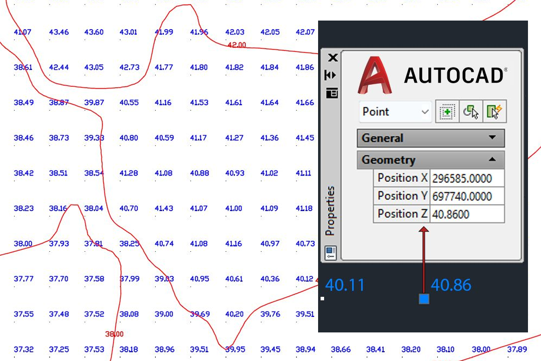
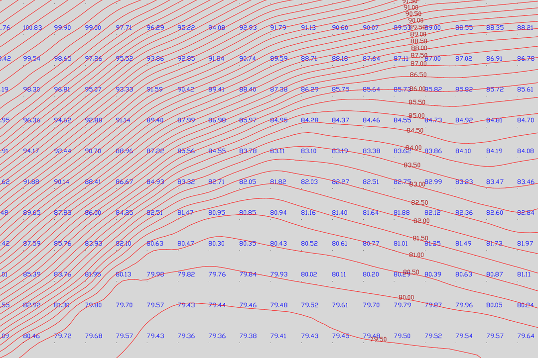
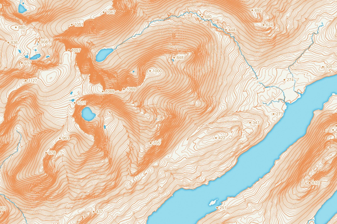
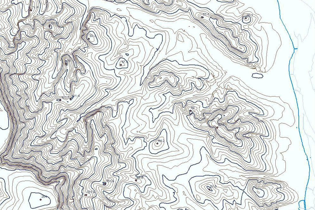
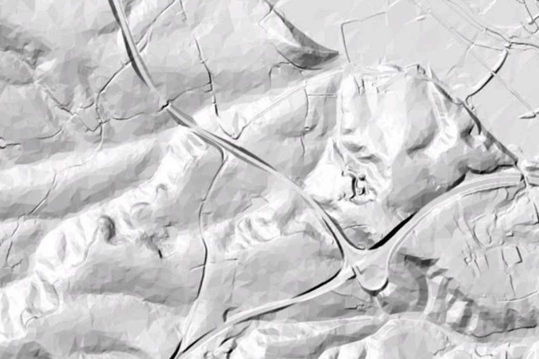
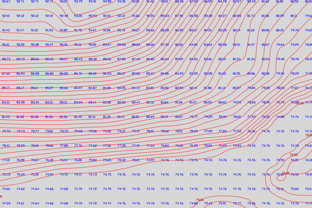

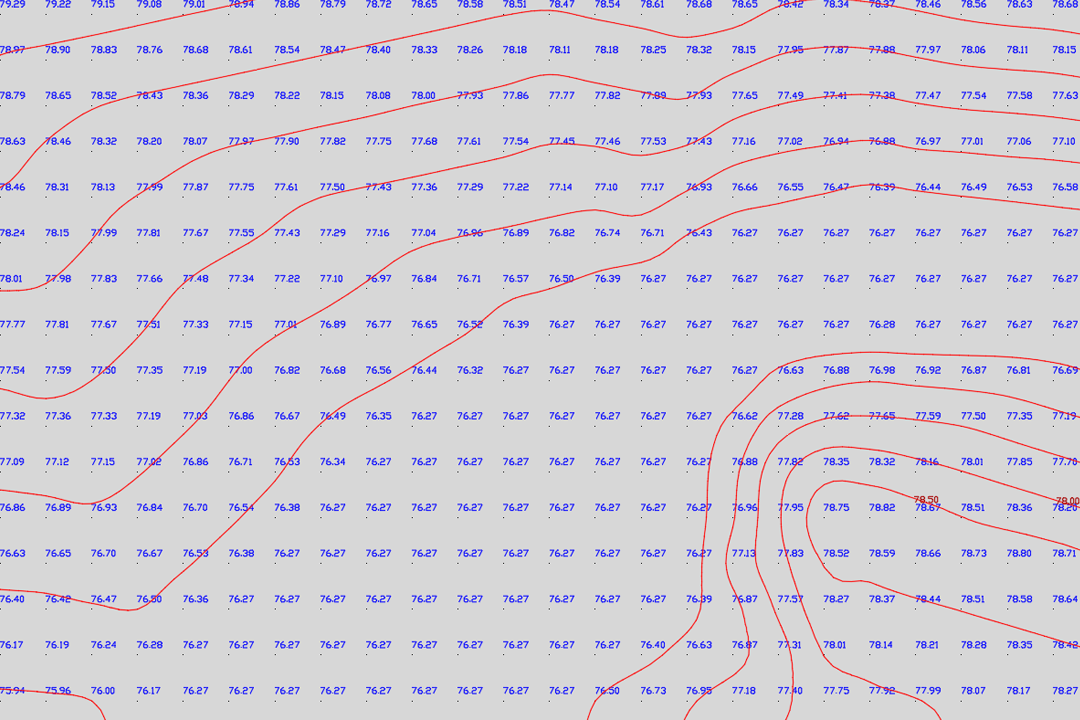
OS Terrain 5 DTM points loaded into AutoCAD - each post carries X, Y coordinates and a Z elevation value on the British National Grid. DTM grid with blue elevation labels and red contour lines - contours generated at your chosen interval from the 5-metre height model. Colour-shaded terrain relief built from OS Terrain 5 ASCII grid data - ideal for landscape assessment, flood modelling and visual impact studies. Contour-only output on a clean white background - ready for overlay onto site plans, engineering drawings or planning submissions. Hillshaded 3D terrain surface rendered from the OS Terrain 5 digital terrain model in a GIS environment. DTM grid points combined with generated contour lines - showing how the 5-metre posts translate into smooth, usable contour geometry. Layered contour visualisation with elevation shading - the same OS height data styled for presentation and report graphics. Terrain 5 height points on relatively flat ground - the 5-metre grid captures subtle elevation changes that matter for drainage and earthworks design.
© Crown copyright and database rights 2026 OS AC0000848283
Download DTM Samples
DTM Only
DWG | DTM Points ↓ DXF | DTM Points ↓Contours Only
DWG | 2m Contours ↓ DXF | 2m Contours ↓All Layers (DTM + Contours + MasterMap)
DWG | All Layers ↓ DXF | All Layers ↓ASCII Grid
OS Terrain 5 ASCII ↓OS Terrain 5 - Digital Terrain Model with Optional Contours
Ordnance Survey Terrain 5 is a 5-metre resolution digital terrain model covering the whole of Great Britain. Every grid post carries an X, Y coordinate on the British National Grid and a Z elevation value in metres above Ordnance Datum (Newlyn). We deliver the data as DWG or DXF for immediate use in AutoCAD, Civil 3D, BricsCAD and all major CAD platforms - or as an ASCII grid file for GIS, surface modelling and 3D visualisation workflows.
Why Order Height Data from UK Map Centre?
Ordnance Survey supplies OS Terrain 5 as an ASCII grid - a raw text file of elevation values arranged on a 5-metre grid. That format works well in GIS software and surface modelling tools, but it cannot be opened directly in AutoCAD or other CAD packages. We solve that by converting the ASCII grid into clean DWG and DXF geometry with every height point placed at its correct X, Y, Z position - ready to snap, measure and build on the moment you open the file.
CAD-Ready DTM Points
Every 5-metre grid post placed as a 3D point or block at its true OS National Grid position with the Z value set to metres above sea level. Open the file in AutoCAD and your terrain surface is already there - no import wizards, no coordinate conversion, no guesswork.
Contours at Your Interval
OS supplies contours only at 5-metre intervals. We generate contour lines from the raw grid at 0.5m, 1m, 2m or 5m spacing - true 3D polylines with Z values in every vertex, placed on a dedicated CAD layer ready for earthworks calculations and cross-sections.
ASCII Grid for GIS & 3D
Need the raw elevation grid? We supply the OS Terrain 5 ASCII file trimmed to your site area or as the full 5km x 5km tile - ready for import into QGIS, ArcGIS, Global Mapper, Civil 3D or any surface modelling application that reads ASC format.
Bolt-On: MasterMap Base Mapping
Add OS MasterMap Topography Layer as a base map underneath your terrain data. Buildings, roads, boundaries and vegetation on named CAD layers - giving your height model the context it needs for site design, planning and analysis.
Updated quarterly - OS Terrain 5 is refreshed every three months (January, April, July, October), so your elevation data reflects the latest survey revisions.
Flexible coverage - order exactly the area you need, from a single field to an entire catchment. The data is clipped to a rectangular extent or a custom site boundary and delivered by email or download link.
Who Uses OS Terrain 5?
Height data underpins a wide range of professional workflows. Architects and engineers use the DTM for site grading, cut-and-fill calculations and foundation design. Civil engineers model drainage paths, flood risk zones and road gradients. Environmental consultants run viewshed analysis, landscape character assessments and visual impact studies. Renewable energy planners assess wind exposure and solar shading. Forestry managers map slope gradients for harvesting plans. Utility companies route pipelines and cables across terrain profiles.
Contour Intervals Explained
A 0.5-metre contour interval captures fine terrain detail for earthworks, drainage design and level surveys. A 1-metre or 2-metre interval suits site-wide grading plans and planning submissions. The standard 5-metre interval is useful for regional landscape assessment, viewshed analysis and route planning across larger areas. All contour intervals are derived from the underlying 5-metre OS Terrain 5 grid - the tighter intervals interpolate between the original height posts to produce usable contour geometry for guideline and planning purposes.
Delivery Formats
Choose the format that fits your software and workflow:
- DWG - native AutoCAD format with full layer support, best for Autodesk workflows including Civil 3D and Revit
- DXF - universal CAD exchange format, opens in AutoCAD, BricsCAD, MicroStation, LibreCAD and virtually every CAD application
- ASCII Grid (.asc) - raw elevation grid for GIS analysis, surface modelling and 3D terrain rendering in QGIS, ArcGIS, Global Mapper and FME
All CAD files are georeferenced to the British National Grid (EPSG:27700). The DWG and DXF outputs include DTM points on one layer and contour lines (if selected) on a separate layer - so you can toggle terrain and contours independently.
CAD Software Compatibility
- AutoCAD by Autodesk
- Civil 3D
- BricsCAD
- MicroStation
- Draftsight
- LibreCAD
- Global Mapper (ASCII grid import)
- QGIS (ASCII grid and contour shapefile)
- ArcGIS (ASCII grid raster surface)
- … all CAD packages that read DWG or DXF
Further Reading
Guides and tutorials to help you work with OS height data and terrain models:
- Turning an ASC File into Contours in QGIS
- Guide to OS Contours and Terrain Height Data
- How to Make a Scaled Plot from a DXF or DWG in AutoCAD LT
- OS Vector and Raster Mapping Fully Explained
- OS CAD Maps with Additional Layers - DTM, Contours and Aerial
About UK Map Centre LLP


Alternative Products:
OS MasterMap for CAD 3D OS MasterMap with Building Heights Extracts: PDF | JPG | TIFF - 1:1250